
Everyone seems to have a separate cable from the alternator, with the starter and house batteries connected to the pins numbered 1 and 2 respectively.Īny useful suggestions (please don't tell me to rewire the boat) about replacement and wiring would be greatly appreciated.
#Battery isolator switch wiring diagram manual#
However, I have not been able to find any manual for this specific Guest model, nor have I been able to find any reference to someone wiring up the isolator in this fashion. I intend to buy a replacement part with a similar capacity. My assumption is that, after 14 years, the battery isolator has failed.

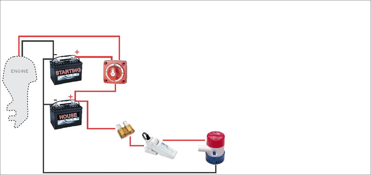
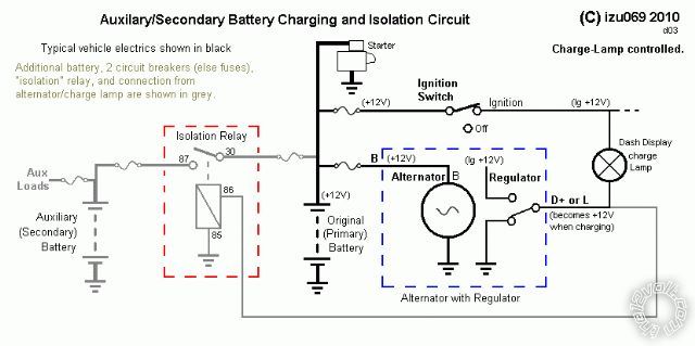
When running the motor (and I have turned off the solar charger/MPPT Controller) at about 2000rpm, on the voltmeter I am getting a reading of 14.28VDC at pin 1 but only 12.38VDC at pin labelled A. There is nothing attached to the third pin numbered 2. The house cable goes to the pin labelled A. On top of the battery isolator, the cable from the starter motor/starter battery goes to the pin numbered 1. (There are also cables running to the generator, irrelevant for current purposes.) On the other side of that switch the + goes to the starter battery itself and it is from that side of the switch that a cable goes to the battery isolator. Rather, the cable from the alternator goes to the starter motor then it runs to the starter battery on/off switch. There is no direct cable from the alternator to the battery isolator. The battery isolator has 3 pins on the top, ordered 1, A and 2. It is model 2430, apparently no longer made. I have located the Guest battery isolator behind the main 12V circuit panel.

My issue is that, when running the motor, the house batteries are not charging.

I have 1 AGM starter battery (which starts both the motor and the generator) and 3 x AGM house batteries. My system seems to work well and I'm reluctant to disturb it unless a more knowledgeable forumite can point out its shortcomings.Bogart is a 2007 Hunter 45CC equipped with generator. My installation obviously has separate wires from starter and alternator. On the other hand the wiring diagram for the Yanmar 2GM20F engine shows the alternator output joined to starter motor and then going to the battery via an isolator switch, which thus controls both the load and charging circuits. On the face of it I can't see anything wrong with this arrangement: the alternator diodes should prevent any current leakage from the batteries when the boat is not in use and the diodes can't be blown due to having an open circuit on the alternator output. Therefore the batteries are not truly isolated when the switches are open because their charging circuits are still connected. The alternator output is permanently connected to the batteries via a diode splitter. the starter motor and domestic loads respectively. The engine and domestic batteries each have their own isolator switch, but these only control the load circuits i.e. I've been investigating the wiring of my new (to me) boat.


 0 kommentar(er)
